

Geometric Dimensioning and Tolerancing (GD&T)
Introduction to GD&T
Geometric Dimensioning and Tolerancing (GD&T) is a symbolic language used to convey design and manufacturing requirements for mechanical parts. It ensures that engineers and manufacturers have a clear understanding of how each feature on a part should be dimensioned and controlled. GD&T eliminates ambiguity and promotes precise communication, resulting in accurate parts that function as intended.
GD&T is widely used in industries such as automotive, aerospace, manufacturing, and engineering, where precision and quality are essential for successful product development and assembly.
GD&T Symbols
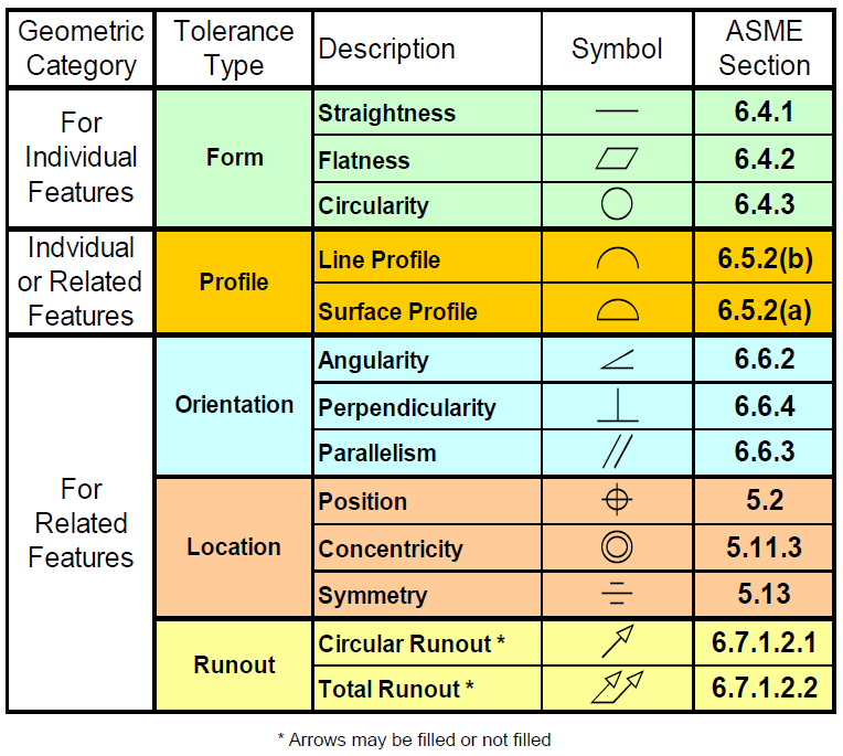
GD&T uses various symbols and annotations to specify the allowable variations in form, size, orientation, and location of features on a part. Each symbol has a specific meaning and tolerance zone that designers and manufacturers must adhere to during the production process.
Some common GD&T symbols include:
- Diameter (⌀): Used to specify the size of a circular feature, such as a hole or shaft.
- Circularity (○): Indicates how closely a feature's actual shape matches a perfect circle.
- Flatness (□): Specifies the flatness of a surface relative to a perfect plane.
- Perpendicularity (⊥): Describes the perpendicular relationship between two features or surfaces.
- Concentricity (◉): Specifies the location of one feature relative to another feature's central axis.
- Parallelism (‖): Indicates the parallel relationship between two surfaces or features.
- Position (⌖): Defines the location of a feature in relation to a reference point.
Understanding these symbols is crucial for accurate manufacturing and proper assembly of mechanical parts.
Importance of GD&T
GD&T plays a vital role in manufacturing and engineering processes due to its numerous benefits. Some of the key reasons GD&T is essential include:
- Interchangeability: GD&T ensures that parts are interchangeable, meaning they can be easily replaced or used in different assemblies, reducing inventory and production costs.
- Quality Improvement: By defining precise tolerances, GD&T helps improve the quality and functionality of mechanical parts, reducing defects and ensuring optimal performance.
- Cost Savings: Accurate dimensioning and tolerance specifications lead to efficient manufacturing processes, minimizing rework and waste, thus saving time and money.
- Clear Communication: GD&T provides a standardized and unambiguous language for communicating design requirements between designers, engineers, and manufacturers, reducing misunderstandings and errors.
- Precision Engineering: GD&T enables engineers to design and manufacture complex parts with high precision, resulting in products that meet strict performance requirements.
- Compliance with Standards: GD&T ensures that parts are produced in accordance with industry standards and regulations, enhancing product safety and reliability.
History of GD&T
In the early 1940s, during World War II, Stanley Parker, while working at the Royal Torpedo Factory in Scotland, noticed that functional parts were being rejected due to out-of-tolerance measurements. To address this issue, he developed tolerancing practices to meet functional requirements, leading to the birth of Geometric Dimensioning and Tolerancing (GD&T). Parker published his work on GD&T in 1940, titled "Notes on Design and Inspection of Mass Production Engineering Work," followed by another publication in 1956 called "Drawings and Dimensions." He introduced the concept of "True Position" and is credited as the originator of GD&T.
In the 1940s, the US military developed the first standards for GD&T. MIL-STD-8 was published in 1949 and revised in 1953 to include GD&T "Rule 1." Subsequently, in 1957, the American Society of Mechanical Engineers (ASME) published their first standard incorporating GD&T, known as ASA Y14.5. Over the years, ASME Y14.5 has been revised approximately every decade to accommodate new concepts and technology, with the latest revision released in 2018.
Alongside ASME standards, the International Organization for Standardization (ISO) has also published popular GD&T standards used globally. In 1996, the ISO Technical Committee 213 was formed to create and maintain ISO Geometrical Product Specifications (GPS). To compare the usage of GD&T standards between ASME and ISO, one can refer to "A Comparison of GD&T Standards: ISO GPS vs. ASME Y14.5." These standards have played a pivotal role in ensuring accurate communication of design requirements and precise manufacturing practices across various industries worldwide.
Development by the U.S. Department of Defense (DoD)
The history of GD&T dates back to the early 1940s when the U.S. Department of Defense recognized the need for a more standardized and precise method of dimensioning and tolerancing. Traditional methods were often ambiguous and lacked control over manufacturing and inspection processes.
ASME Y14.5 Standard
In 1982, the American Society of Mechanical Engineers (ASME) published the first version of the ASME Y14.5 standard, titled "Dimensioning and Tolerancing." This standard introduced the principles of GD&T, providing engineers and manufacturers with a common language to communicate design requirements accurately.
Evolution and Revisions
Since its initial release, the ASME Y14.5 standard has undergone several revisions to keep pace with technological advancements and industry needs. The latest revision, ASME Y14.5-2018, continues to be a globally recognized reference for GD&T.
GD&T Adoption in Industries
Over the years, GD&T has gained widespread adoption across various industries, including automotive, aerospace, manufacturing, and engineering. Its precise and unambiguous language has proven to be critical in ensuring the consistent quality and interchangeability of parts in complex assemblies.
CAD and CAM Integration
With the advent of computer-aided design (CAD) and computer-aided manufacturing (CAM) technologies, the implementation of GD&T has become more seamless and efficient. Modern software tools enable designers to specify GD&T directly in CAD models, which can then be used for automated manufacturing processes.
Global Impact
GD&T has not only gained popularity in the United States but also across the globe. Its use has become an integral part of international standards like ISO 1101, which provides a framework for GD&T application worldwide.
ASME Y14.5-2009
[Revision of ASME Y14.5M-1994 (R2004)]


0 Comments